 Electronics Weekly
 As aerospace platforms evolve to support more data-intensive capabilities, ranging from real-time video and sensor fusion to advanced radar, traditional data buses such as MIL-STD-1553 are no longer sufficient. Their low throughput and legacy architecture cannot keep pace with mission-critical systems that now demand the bandwidth, speed and flexibility of Ethernet-based fibre optic links.
Fibre optics built on IEEE 802.3 standards offer data rates from 1Gbps to 400Gbps, enabling the robust digital infrastructure modern avionics require. This shift introduces a challenge, however: high-speed optical systems are more susceptible to signal degradation from jitter, interference and attenuation. To maintain signal integrity and achieve the low bit error rates (BER) essential for flight and mission safety, designers are turning to a long-established tool from long-haul networking: forward error correction (FEC).
High-speed optical links
IEEE 802.3 Ethernet over fibre provides a scalable standard for communications, with up to 400Gbps transmission speeds. While this opens new performance frontiers, it also introduces greater signal integrity concerns. Unlike older systems, where low data rates masked minor losses, high-speed optical links are unforgiving, especially as data encoding methods such as pulse amplitude modulation with four levels (PAM4) reduce voltage margins and increase susceptibility to noise.
In this new context FEC emerges as an essential tool for achieving reliable communication in noise-prone environments.
Understanding signal integrity
Signal integrity in data transmission hinges on one critical factor: the signal-to-noise ratio (SNR). It determines the system’s ability to distinguish transmitted information from background interference accurately. It is expressed in decibels (dB) using the formula:
SNR (dB) = 10 · log₁₀ (P_signal / P_noise)
In applications with high SNR data errors are rare. The effective SNR drops as data rates increase and noise sources accumulate, whether from laser jitter, imperfect connectors or receiver limitations. Unless additional measures are taken a system functioning well at 1Gbps may experience unacceptable BER at 25Gbps.
For critical avionics functions even minor data corruption can have significant consequences. While some applications might tolerate a BER of 10⁻⁴ safety-sensitive systems often demand BERs as low as 10⁻¹². Achieving such performance in high-speed environments requires costly upgrades to components or the strategic use of FEC.
From detection to correction
Traditional error-handling approaches, such as parity bits, checksums and cyclic redundancy checks, can detect errors but cannot correct them. These techniques are lightweight and fast, but when used alone they require the system to request retransmission, which is impractical or impossible in many real-time or one-way communication settings.
FEC solves this problem by adding redundancy directly into the data stream. It appends additional ‘parity’ or ‘check’ bits to each data block, enabling the receiver to detect and correct certain errors without retransmitting them. The most commonly used FEC scheme in optical communications is Reed-Solomon (RS) coding, such as RS(255,239), which encodes 239 data symbols with 16 parity symbols. This configuration allows the receiver to correct up to eight symbol errors per block.
FEC improves effective BER by orders of magnitude, often from 10⁻⁴ to 10⁻¹². It effectively increases the system’s noise tolerance without drastically improving laser power, connector quality or photodetector performance.
Design trade-offs
FEC is not without cost. Each coding scheme introduces symbol overhead, increases processing complexity and adds latency due to block-based encoding and decoding.
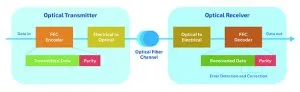
Figure 1: Changes at both ends of the link increase complexity but also provide scalability and future-proofing
For example, RS(255,239) adds about 6.3% overhead. Designers can increase the transmission rate to compensate or accept the reduced throughput. Meanwhile, block processing latency becomes more significant at lower data rates. A 10Gbps system might see only 1µs of latency, equivalent to 300m of fibre delay, whereas a 1Gbps link could incur 10µs, or 3km of equivalent delay.
The benefits of improved BER must be weighed against added complexity and system delay, particularly in latency-sensitive aerospace applications.
Not every fibre optic link in an aircraft or satellite system needs FEC. When data rates are low (for example, 1Gbps to 2Gbps), it’s often more cost-effective to improve BER by enhancing individual link components, such as increasing laser output power, using a diode with a higher extinction ratio, selecting a more sensitive photodetector and reducing connector losses.
At speeds of 10Gbps and above these individual improvements may not suffice. The compounded effects of laser jitter, inter-symbol interference (ISI), receiver noise, and bandwidth limitations cannot always be mitigated with hardware alone. FEC becomes a strategic necessity to close the link budget and ensure system robustness under real-world conditions.
In addition, using FEC implies co-ordinated changes at both ends of the link, the transmitter and receiver. While this may increase upfront system complexity, it also provides an architectural pathway for scalability and future-proofing as data requirements continue to rise.
FEC and PAM4
One factor driving the urgency of FEC adoption is the increasing use of PAM4 in high-speed links. PAM4 enables transmission of two bits per symbol, effectively doubling data rates without increasing the baud rate. This comes at a cost however, the logic level amplitude is reduced to one-third of that in non-return to zero modulation, degrading SNR by nearly 9.5dB at comparable BER.
This reduced margin means that PAM4-based systems are inherently noisier and more error-prone, making FEC indispensable in such contexts. PAM4 systems are often designed with FEC as a built-in feature to enable acceptable BER performance, even under ideal laboratory conditions.
Redesigning circuits to reduce noise can be expensive and time-consuming, whereas incorporating FEC may be more economical and effective, especially when dealing with standard components or existing platforms.
Noise sources in optical links
Aerospace systems using fibre optics face a variety of noise sources throughout the signal path, including:
- Optical transmitter: laser modulation jitter and low ER can reduce signal clarity
- Fibre cable: connector losses and modal dispersion can degrade signals, especially in multi-fibre wavelength-division systems
- Optical receiver: PIN diode noise, transimpedance amplifier input noise and sampling jitter contribute to BER
- Converter electronics: ISI and bandwidth limitations on either side of the link further constrain performance.
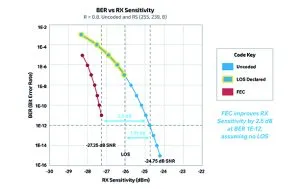
Figure 2: Receiver sensitivity relies on consistent performance thresholds for transmitter, fibre, receiver and FEC logic
In aggregate these issues reduce the system’s effective SNR. FEC provides a buffer, improving BER by 6-10dB depending on the coding scheme and allowing systems to meet stringent performance targets without over-engineering each subsystem.
Even in short-haul aerospace applications receiver sensitivity can become the limiting factor. If the receiver declares a loss of signal at a threshold above where FEC could still recover the data, the benefit of FEC is lost.
For example, a system might achieve an uncoded BER of 10⁻⁴ at -24.75dBm. FEC could extend performance to -26.0dBm, but if the receiver triggers LOS at -25dBm, the extra coding gain cannot be utilised. Engineers must therefore design the complete system: transmitter, fibre, receiver and FEC logic with consistent performance thresholds in mind.
The role of FEC
Whether compensating for PAM4 signal degradation or managing noise in 25Gbps links, FEC offers improved reliability, lower BER and system resilience.
Its use requires careful consideration of latency, complexity and implementation cost trade-offs, so the decision to implement FEC should be grounded in a full-system evaluation that considers not just component specs but real-world noise sources and architectural constraints.