 Electronics Weekly
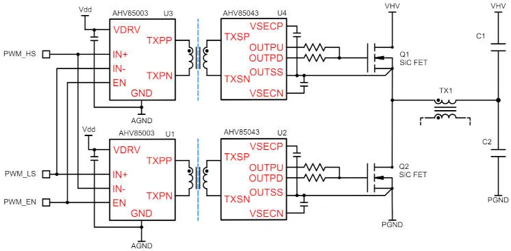
AHV85003 is the transmitter and AHV85043 is the receiver, which need to be connected together through an isolation transformer.
“With selectable gate-to-source voltages of 15V, 18V and 20V, and adjustable regulated negative voltage, designers can swap between SiC FETs from different vendors without redesigning their boards,” claimed the company.
The voltage selection here is through different variants of the ICs, indicated through ‘KxxESTR’ suffixes – for example, the part numbers for the 15V chip set are AHV85003K15ESTR and AHV85043K15ESTR.
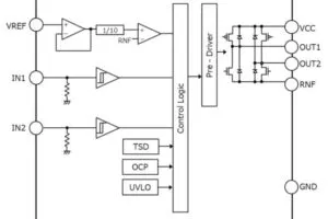
A nominal 12V power supply (10.5 – 13.2V) is required on the primary side to feed both ICs. This will need to provide, for example, 12.5mA for 100kHz switching.
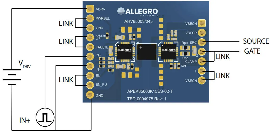 So far, only Sunlord’s 5 x 3.8 x 3.2 LTW4638A-P-C05TF transformer is specified as the intervening transformer – which provides functional isolation and is not rated for safety isolation. This is the part used on the chipset’s APEK85003K15ES-02-MH evaluation board.
On the input side the required signals are a PWM input waveform – for which two inputs are provided to give a choice of an inverted PWM or direct – and an enable signal.
The PWM signals are compatible with 5V logic, and lower voltage logic that can provide at least 2.0V for a ‘high’ level.
If the PWM waveform is stopped, the primary side IC continues to transmit power to the secondary side IC through the transformer.
“As a result, no bootstrap or isolated supply is required to get the isolated side of the driver chipset started, so the chipset is ready to respond immediately to signals at the [input] pins,” said Allegro.
At the output, drive is up to 6A for gates up to 130nC.
Typical propagation delay is 85ns with <50ns skew and pulse-width-distortion.
Greater than 100V/ns dv/dt common-mode transient immunity is claimed.
Packaging in all cases is 4 x 4mm 20pad QFN, and the devices are automotive qualified to AEC-Q100 Grade 1.