 Electronics Weekly

The aim was to see if the faster photodiode types can operate quickly in common collector mode.
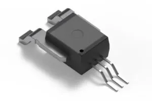
They consist of an infra-red led and a fast npn transistor with its base connected to a co-packaged reverse-based photodiode.
And there are layers and layers of subtly in their operation.
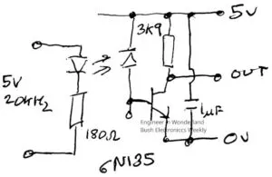
The conventional circuit (right) has the photodiode connected to 5V, and a collector resistor also connected to 5V.
With a 4k1 collector resistor and 16mA drive into the led, the chosen (read ‘cheapest on ebay’) 6N135 is supposed to beat 1.5μs for both turn on and turn off, with typical figures of 90ns and 800ns.
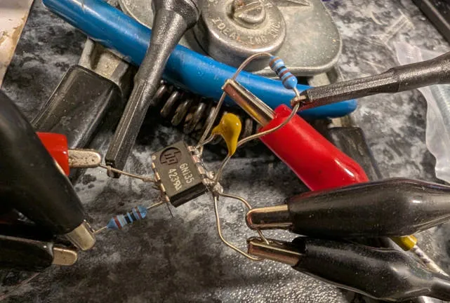 With a 3k9 resistor soldered on in a rats nest (left), this one managed 170ns and 1.5μs.
UPDATE: This slow turn-off looked too suspicious, so another batch of 6N135 were bought (also via ebay), and one picked from the second batch had 700ns rise and fall times (to 90/10%) in the same circuit. The first one has ‘HP’ moulded into its plastic case, and I wonder if it is a reject that someone sold, or it is a different HP part that has been re-marked – the marking is quite. the second one has ‘GI’ printed on its case, which I presume is General Instruments.
Due to this, take the slow turn-off of the HP part tested into account through the rest of this blog. END UPDATE
This isolator is for a motor speed controller interface and, in this case, the common emitter circuit would default the motor to ‘full-speed’ (rather then the safer ‘stop’) if the led stopped shining for any reason.
Having looked around, most interfaces I could find instead use a common collector connection, with the output resistor in the emitter circuit, which defaults the motor to ‘stop’ if the led stops.
Common collector connection is fine for bog-standard opto-couplers with photo-transistor outputs, but the slow turn-off of these types makes the pwm-to-voltage conversion non-linear unless unusually low pwm frequencies are adopted.
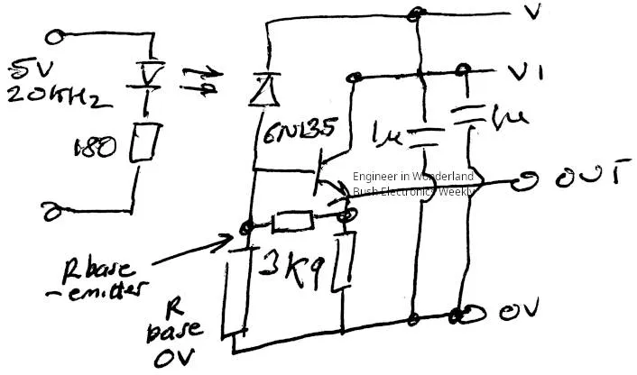
So, can a faster photo-diode type opto-coupler work in a common-collector circuit? (right)
App notes were impossible to find, hence the experiment.
Shorting the photo diode cathode to the emitter (connecting V to V1 in the diagram) resulted in
Trise = 2μs, Tfall = 25μs with a 5V output supply
Trise = 4μs, Tfall = 19μs with a 10V output supply (to ~90% and 10% of 10V)
Slower turn on and far slower turn off.
How about biasing the photo-diode properly, connecting the photo diode (V) to 10V and the collector (V1) to 5V?
Trise = 1.2μs, Tfall = 15μs was the result – turn on now splendid, turn off slightly better but still awful.
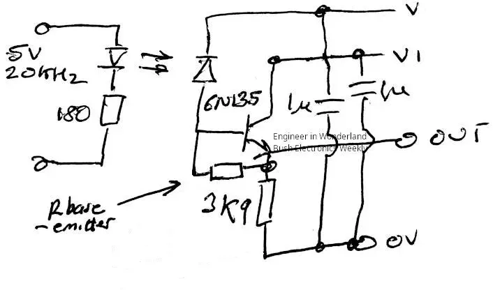 As the npn base is bought out to a package pin on the 6N135, how about a base-emitter resistor to improve turn-off? (in diagram right)
820kΩ gave Trise = 1.4μs, Tfall = 10μs
410kΩ gave Trise = 1.6μs, Tfall = 8μs
80kΩ gave Trise = 2.2μs, Tfall = 3.4μs
44kΩ gave Trise = 3.6μs, Tfall = 2.4μs (too far!)
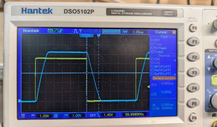 66.6kΩ gave Trise = 2.6μs, Tfall = 3.1μs (right, at 40kHz)
An excellent improvement.
Except that curiosity demanded quickly rolling this ‘best’ base-emitter resistor back into the circuit with the photo-diode shorted to the collector:
Trise = 4.4μs, Tfall = 5.5μs with 5V supply
Trise = 10μs, Tfall = 5.7μs with 10V supply
After which, a cuppa in the warm kitchen was required.
The version with a 10V photo-diode bias and a 5V collector supply, with a 100kΩ preset from base to emitter, could be set to have even ~2.9μs delay on both rise and fall.
Followed by a rail-to-rail output comparator, the pwm would be reconstructed accurately but delayed by a few microseconds, ready for low-pass filtering and buffering with a rail-to-rail op-amp.
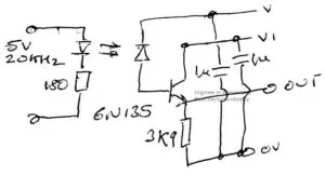
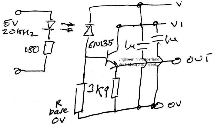 Update, the next day, tried base-to-0V resistors instead of base-to-emitter – (diagram left), results collated in table below (with results from above).
This scheme also works, with ~260kΩ providing balanced ~3μs rise and fall times, but with no apparent benefit over the right base emitter resistor.
| Vphoto diode |
V1 emitter |
emitter load |
R base- emitter |
R base- 0V |
T rise (μs) |
T fall (μs) |
| 5 | 5 | 3k9 | 2 | 25 | ||
| 5 | 5 | 3k9 | 66.6k | 4.4 | 5.5 | |
| 5 | 5 | 3k9 | 820k | 2.9 | 11 | |
| 5 | 5 | 3k9 | 410k | 3.7 | 7.5 | |
| 10 | 10 | 3k9 | 4 | 19 | ||
| 10 | 10 | 3k9 | 67k | 10 | 5.7 | |
| 10 | 10 | 3k9 | 820k | 6.5 | 9.3 | |
| 10 | 10 | 3k9 | 410k | 10* | 5.9 | |
| 10 | 5 | 3k9 | 1.2 | 15 | ||
| 10 | 5 | 3k9 | 820k | 1.4 | 10 | |
| 10 | 5 | 3k9 | 410k | 1.6 | 8 | |
| 10 | 5 | 3k9 | 80k | 2.2 | 3.4 | |
| 10 | 5 | 3k9 | 44k | 3.6 | 2.4 | |
| 10 | 5 | 3k9 | 66.6k | 2.6 | 3.1 | |
| 10 | 5 | 3k9 | 410k | 2.3 | 4.4 | |
| 10 | 5 | 3k9 | 200k | 5* | 2.6 | |
| 10 | 5 | 3k9 | 264k | 3.1 | 3.4 |
Empty box = open circuit * = transistor not saturating well
From these, separate 10V and 5V rails seem to to be the best, with either a little lower than 67k base-emitter resistance, or ~260k base-0V resistance.
Either, it seems, can deliver ~3μs symmetrical rise and fall times
To be continued….